Connector Diagram
The Connector Diagram is a canvas for process and single-line diagrams. You place automation symbols on it — tanks, valves, pumps, switches — and draw pipes between them in the Designer. At runtime the diagram shows which pipes carry the medium, from the state of the symbols: open a valve and the pipes through it light up. It is found in the Chart - OpenBridge section of the Perspective Component Palette as Connector Diagram.

The parts of a diagram:
- Symbols — ordinary Perspective components placed inside the diagram. See Symbols.
- Pipes — the lines between them, drawn in the Designer. See Drawing Pipes.
- Flow — which pipes carry the medium, worked out from the symbols. See Flow.
- User toolbar — the bar at the bottom, where the operator switches the colours, tags and readouts. See User Toolbar.
“Pipe” is used for every kind of line: a pipe, a cable, a duct. What it carries is its medium (water, fuel, power, …).
Symbols
Section titled “Symbols”The Connector Diagram is a container. Drop symbols onto it in the Designer,
and move and size them as in a coordinate container: each has x, y,
width and height under position.
Any component can sit in the diagram, but pipes connect to the automation symbols — Pump, Analog Valve, Switch, Automation Tank and the rest — and only some of them take part in the flow.
The name of a symbol matters: a pipe stores the names of the symbols at its
ends. Give symbols meaningful names (FuelPump1, TankFW) before drawing
pipes; the pipe list in the Designer then reads like the process.
A new diagram is 600 × 400 px. Make it the root of its view, or give it the size of the area the process fills.
Drawing Pipes
Section titled “Drawing Pipes”Pipes are drawn in the Designer, on the diagram itself. At runtime the diagram is display-only: the operator cannot move or draw pipes.
Connection Points
Section titled “Connection Points”Hover over a symbol to see its connection points, one in the middle of each side. The one nearest the pointer shows a +:
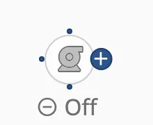
- Draw a pipe: press on the + and drag to a connection point of another symbol. Release on an existing pipe to join it with a T; release in empty space to leave a loose end.
- Move a symbol: press in the middle of the symbol. Pressing the body moves the symbol; pressing the edge draws a pipe.
The diagram routes the pipe with right-angled corners, and re-routes it when you move a symbol:

Changing a Pipe
Section titled “Changing a Pipe”Click a pipe to select it. The round handles on each straight run slide that run sideways, to shape the route by hand; drag an end to connect it somewhere else. The Delete key, or the bin in the toolbar, deletes the selected pipe.

The Editing Toolbar
Section titled “The Editing Toolbar”While you edit, a toolbar sits at the bottom of the diagram:

| Control | What it does |
|---|---|
| Tool | Pipe draws and edits pipes; Section draws background sections. |
| Medium color | The medium of the selected pipe, from the diagram’s medium palette. |
| Pipe size | The thickness of the selected pipe. Default takes the size of its medium. |
| Endpoint | The end mark of the selected pipe end. Shown while a pipe end is selected — click an end of a selected pipe. |
| Delete | Deletes the selected pipe or section. |
| ⚙ | Opens the global settings: the medium palette. |

End Marks
Section titled “End Marks”A pipe end that is not attached to a symbol can carry a mark. The marks also tell the flow where the medium comes from and where it goes:
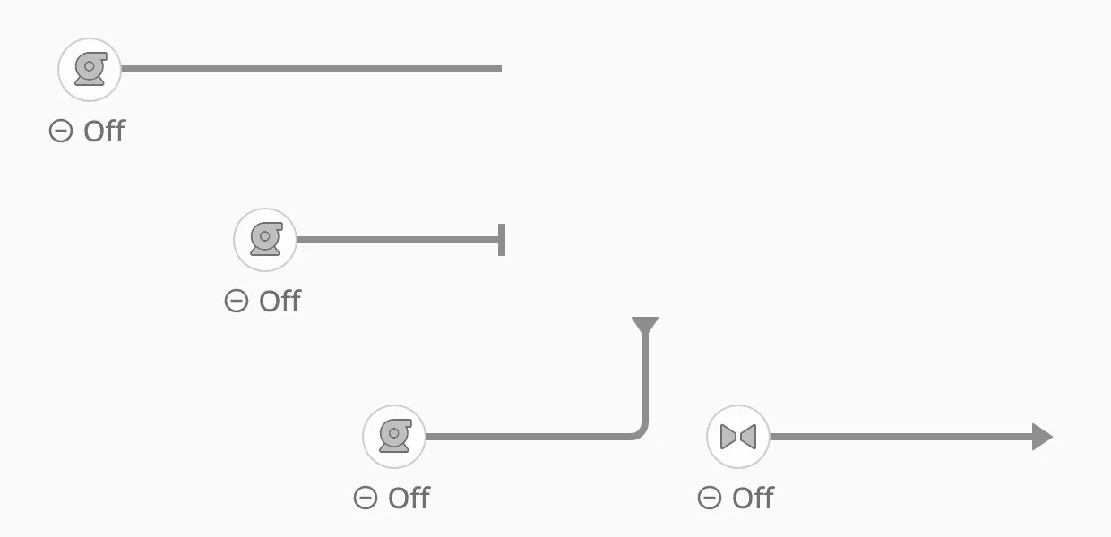
| Endpoint (toolbar) | Value | Meaning |
|---|---|---|
| None | none |
A plain end. |
| Stop | cap |
The pipe ends here. The default for a loose end. |
| Coming from | arrow-in |
The medium arrives here from outside the diagram — a source for the flow. |
| Going to | arrow-out |
The medium leaves the diagram here — a sink for the flow. |
The diagram works out, every time something changes, which pipes the medium flows through. You do not bind the pipes to anything: bind the symbols to the process, and the pipes follow.
The Rule
Section titled “The Rule”A pipe carries the medium when it lies on a path from a source to a different sink. A pipe on no such path is drawn as an empty, grey line — “nothing flows here”, which the operator can tell apart from “no pipe here”.
-
Sources and sinks. A tank is both: the medium can leave it and arrive in it. A loose pipe end marked Coming from is a source, one marked Going to is a sink.
-
Gated symbols let the medium through only while they are open or running:
Symbol Lets the medium through while Analog Valve, Digital Valve openistruePump, Fan, Motor onistrueSwitch, Damper, Automation Button NEW onistrue -
Everything else — a readout, a filter, a symbol without a state — lets the medium through freely, as a fitting would.
-
A pump is not a source. It moves what reaches it; with no tank or Coming from end behind it, the pipes around a running pump stay empty.
-
Junctions (T and cross) always let the medium through.
-
A closed pipe blocks. A pipe whose
stateisclosedblocks the flow, whatever the symbols do.
What each symbol means is built into the module and is the same in every diagram; you cannot change it per view.
Example
Section titled “Example”Two tanks are joined twice: through a valve, and through a pump. The tank on the left is empty, the one on the right half full — the flow does not depend on the level, only on the path.
Valve closed, pump off

Valve open
Pump on

Valve open and pump on

With the valve open but the pipe after it set to closed, there is no longer a
path from one tank to the other, and nothing flows — not even in the pipes
before the valve:

Manual Pipes
Section titled “Manual Pipes”A pipe can opt out of the automatic flow. Set its flow to manual, and it
shows its own state — bind that to a tag or an expression. The flow engine
still passes the medium through a manual pipe; only its look is yours.
| state | Looks like |
|---|---|
open |
The medium flows (coloured, or the flow style in regular mode). |
empty |
An empty pipe. |
closed |
A closed pipe. Also blocks the flow. |
Below, the two pipes around the pump are manual: the one on the left is set to
empty, the one on the right to open, while the flow through the valve is
automatic:

Turning the Flow Off
Section titled “Turning the Flow Off”With flow.enabled set to false, no flow is worked out at all, and every
pipe shows its stored state (by default open) — as if every pipe were
manual:

Embedded Views
Section titled “Embedded Views”A symbol is often reused as a small view — a valve with its readout, bound to a tag path passed as a parameter — and embedded in the diagram. Such an embedded view takes part in the flow as the symbol it holds: an embedded view holding a valve lets the medium through while that valve is open.
An embedded view that holds a diagram of its own is joined to the outer diagram, so the flow continues through it.
Finding a Pipe and Changing Its Properties
Section titled “Finding a Pipe and Changing Its Properties”Every pipe has an id, a short generated name such as cmummicfa1. The
pipes are stored in the diagram’s connections property, keyed by that id:
props.connections.cmummicfa1.stateprops.connections.cmummicfa1.mediumIdprops.connections.cmummicfa1.directionThe id never changes, even when other pipes are added or deleted, so a binding
on props.connections.<id>.<property> stays on the right pipe.
In the Designer: the Pipe Panel
Section titled “In the Designer: the Pipe Panel”Select the Connector Diagram. The Property Editor then shows a pipe panel for it:
- Click a pipe on the canvas, or choose it in the panel’s Pipe list.
Each entry names the two ends and the id, for example
ObcAnalogValve.right → automationTank_0.bottom (cmummicfa1)— this is how you see the id of a pipe. - Below the list, the panel shows the pipe’s bindable properties with their
current values:
state,mediumId,mediumColor,size,visible,directionanddirectionPosition. A value marked (default) is not stored on the pipe; (bound) means it already has a binding. - Click Bind… next to a property to open the Edit Binding dialog on
props.connections.<id>.<property>, or Edit binding… to change an existing one.
Choosing a pipe in the list also selects it on the canvas, so the list is also the way to find which pipe an id belongs to.
In the Property Editor Directly
Section titled “In the Property Editor Directly”Expand props → connections in the Property Editor. Each entry is one pipe,
named by its id; its from.componentId and to.componentId name the symbols at
its ends. Change or bind any property there as on any other component.
From a Script
Section titled “From a Script”The same path works in a script, for example to show a pipe as closed:
self.getSibling('ConnectorDiagram').props.connections['cmummicfa1'].state = 'closed'Pipe Properties
Section titled “Pipe Properties”| Name | Description | Property Type |
|---|---|---|
| state | open, empty or closed. Used as shown for a manual pipe; closed always blocks. Default open. |
value |
| flow | auto (the diagram decides) or manual (the pipe shows its state). Default auto. |
value |
| mediumId | The medium the pipe carries: an id from the medium palette. Empty by default. | value |
| mediumColor | A colour for the pipe directly, instead of a medium: Neutral, Enhanced, Blue, Cyan, Teal, Green, Yellow, Orange, Red, Purple or Indigo. Wins over mediumId when set. See the note below. |
value |
| size | small, medium, large, xl, or inherit to take the size of the medium. Default inherit. |
value |
| visible | Show the pipe. Default true. |
value |
| direction | A flow-direction arrow on the pipe: none, forward (from → to) or reverse. Default none. |
value |
| directionPosition | Where the arrow sits: start, center or end. Default center. |
value |
| from, to | The two ends: the symbol (componentId) and side (direction), a junction, or a loose end with its x, y and end mark (terminal). Maintained by the editor. |
object |
Note: A pipe with both
mediumIdandmediumColorset showsmediumColor. Choosing a medium in the toolbar clearsmediumColor, which is what hands the colour to the medium. If a binding onmediumIdseems to do nothing, check whether the pipe has amediumColor.
direction = forward |
 |
direction = reverse |
 |
size = small |
 |
medium |
 |
large |
 |
xl |
 |
Mediums and Colours
Section titled “Mediums and Colours”The medium palette is the list of mediums the diagram carries, each with a name, a colour and a pipe size. Edit it with the ⚙ button in the editing toolbar:
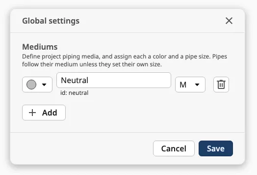
Assign a medium to a pipe with Medium color in the toolbar. Re-colouring a
medium in the palette repaints every pipe that carries it. The palette is stored
in userToolbar.mediumColors, and also makes up the legend of the
user toolbar.
View Mode
Section titled “View Mode”viewMode decides how pipes that carry the medium are drawn:
medium
regular (default)

medium— in the colour of the pipe’s medium.regular— in one neutral flow style, whatever the medium.
Empty and closed pipes look the same in both modes. The operator switches the mode with Color in the user toolbar.
User Toolbar
Section titled “User Toolbar”At runtime a toolbar at the bottom of the diagram lets the operator change what the diagram shows:

- Color switches
viewModebetweenmediumandregular. - The legend lists the mediums with their colours.
- ID-tag and Readout switch
userToolbar.showTaganduserToolbar.showReadout. The diagram does not show or hide anything itself: bind the symbols’hasTagandshowReadoutStackto these two properties.
Properties
Section titled “Properties”userToolbar sub-properties:
| Name | Description | Property Type |
|---|---|---|
| showViewModeToggle | Show the Color button. Default true. |
value |
| showLegend | Show the legend. Default true. |
value |
| showEmptyLegend | Include the colour of an empty pipe in the legend. Default false. |
value |
| showTagToggle | Show the ID-tag button. Default true. |
value |
| showTag | Whether ID-tag is on. Written by the button. Default false. |
value |
| showReadoutToggle | Show the Readout button. Default true. |
value |
| showReadout | Whether Readout is on. Written by the button. Default false. |
value |
| mediumColors | The medium palette: a list of mediums with id, label, color and size. |
array |
showUserToolbar turns the whole toolbar off.
Sections and Mini-map
Section titled “Sections and Mini-map”Sections are background boxes that group part of the diagram — a room, a deck, a system — with a label on the top edge. Draw them with the Section tool; they never affect the pipes or the flow.

A section with a detail view becomes a card the operator can click at
runtime: its label gets a chevron, and a click opens that view in a dialog over
the diagram. Set zones.<id>.detailView to the view, and zones.<id>.viewParams
to extra parameters; the view also receives zoneId and zoneLabel.
The mini-map is a small overview in a corner of the diagram, with zoom
buttons. Sections are drawn solid on it, and a section with an alerting symbol
inside gets a coloured dot. Turn it on with minimap.enabled:

Properties
Section titled “Properties”| Name | Description | Property Type |
|---|---|---|
| zones | The sections, keyed by id, each with x, y, w, h, label, detailView and viewParams. zones.<id>.label can be bound. |
object |
| minimap.enabled | Show the mini-map. Default false. |
value |
| minimap.corner | Corner of the mini-map. Default top-right. |
value |
| view.zoom | Zoom of the diagram: 0.5, 1 or 1.5. Written by the mini-map. Default 1. |
value |
Properties
Section titled “Properties”Properties not covered in the sections above:
| Name | Description | Property Type |
|---|---|---|
| editable | Allow drawing and changing pipes in the Designer. Default true. Pipes are never editable at runtime. |
value |
| gridSize | Grid, in px, that loose pipe ends snap to. Default 24. |
value |
| viewMode | regular or medium. See View Mode. Default regular. |
value |
| flow | flow.enabled turns the flow on or off. Default on. |
object |
| connections | The pipes, keyed by id. See Finding a Pipe. | object |
| nodes | The junctions (T and cross) the pipes share. Maintained by the editor. | object |
| style | Standard Perspective style object. | object |
Component Events
Section titled “Component Events”| Event | Description | Event Object |
|---|---|---|
| onZoneExpanded | Fired when a section card opens its detail view. | event.zoneId, event.label |
| onZoneCollapsed | Fired when the detail view closes. | event.zoneId, event.reason: close-button, outside, escape or removed |
Examples
Section titled “Examples”Example 1 — Fuel Transfer Between Two Tanks
Section titled “Example 1 — Fuel Transfer Between Two Tanks”- Drop a Connector Diagram into a view and make it the size of the view.
- Drop two Automation Tanks, an Analog Valve and a Pump onto it.
Name them
TankA,TankB,TransferValveandTransferPump. - Bind each tank’s
valueto its level tag, the valve’sopento the valve feedback and the pump’sonto the pump’s running signal. - Draw a pipe from the bottom of
TankAto the left ofTransferValve, and on from its right to the bottom ofTankB. Draw a second path throughTransferPump, joining the first pipes with T junctions. - In the ⚙ settings, add a medium
Fuelwith a colour, select the pipes and choose Fuel as their medium. - Set
viewModetomedium.
In a session, the pipes through the valve fill with the fuel colour when the valve opens, and those through the pump when it runs. Nothing more is bound.
Example 2 — Show a Pipe as Out of Service
Section titled “Example 2 — Show a Pipe as Out of Service”-
Select the diagram and click the pipe on the canvas; the pipe panel shows its id, for example
cmummicfa1. -
Click Bind… next to
state, and bind it with an expression:if({[default]Fuel/Line2/OutOfService}, 'closed', 'open')
While the tag is true, the pipe is drawn closed, and no flow passes it.
Found an error or something unclear?
Tell us what is wrong, confusing or missing on this page.
Built on the OpenBridge Design System